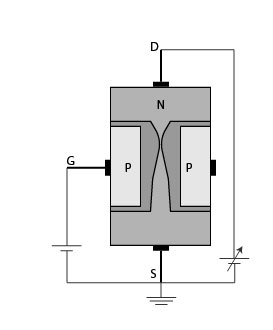

When you turn on a Mosfet by supplying the required voltage to the gate pin, it will remain on unless you supply 0V to the gate. When the applied voltage is positive, the motor will be in the ON state and if the applied voltage is zero or negative, the lamp will be in OFF state. The gate input voltage V GS applied with the help of an input voltage source. The below circuit shows the MOSFET operating as a Switching device for turning ON and OFF of the lamp. The most common application of a MOSFET is using it as a switch. The other popular MOSFETs are IRFZ44N, BS170, IRF520, 2N7000, etc As you can see the Gate, Drain, and Source pin are listed below, do remember that the order of these pins will change based on the manufacturer. The most commonly used package for MOSFET is To-220, for a better understanding let’s take a look at the pinout of the famous IRF540N MOSFET (shown below). In the below image, the symbol of N-Channel MOSFET is shown on the left and the symbol of P-Channel MOSFET is shown on the right. The body terminal will always be connected to the source terminal hence, the MOSFET will operate as a three-terminal device. In general, the MOSFET is a four-terminal device with a Drain (D), Source (S), gate (G) and a Body (B) / Substrate terminals. The isolation of the controlling Gate increases the input resistance of the MOSFET extremely high in the value of the Mega-ohms (M Ω ). The main difference between FET and MOSFET is that MOSFET has a Metal Oxide Gate electrode electrically insulated from the main semiconductor n-channel or p-channel by a thin layer of Silicon dioxide or glass. We will get into details later in this article. Practically speaking, MOSFET is a voltage-controlled device, meaning by applying a rated voltage to the gate pin, the MOSFET will start conducting through the Drain and Source pin. In some cases, MOSFETs are also be called IGFET (Insulated Gate Field Effect Transistor). So a MOSFET can be called the advanced form of FET. MOSFET stands for Metal Oxide Field Effect Transistor, MOSFET was invented to overcome the disadvantages present in FETs like high drain resistance, moderate input impedance, and slower operation. If you want to skip the theory, you can check out the article on popular MOSFETs and where to use them to speed your part selection and design process.
#Fet transistor characteristics how to
In this article, we will learn the Basics of MOSFET, its internal construction, how it works, and how to use them in your circuit designs. Compared to BJT, MOSFET can handle high voltage and high current, hence it is popular among high power applications. Next to BJT, the widely used power switches are MOSFETs. The most basic of them all is the BJT, and we have already learned the working of BJT Transistors.
#Fet transistor characteristics driver
are essential devices used in the design of many circuits ranging from a simple driver circuit to complex Power rectifiers and Inverters. Power Electronic Switching components like BJT, MOSFET, IGBT, SCR, TRIAC, etc.


 0 kommentar(er)
